Pressure overview
On this form you find the pressure information for each compartment, where the fluids are in hydrostatic equilibrium. This form is directly linked to the information on the Fluid Levels form (i.e. Fluid Leg, GOC and FWL), and on the Fluid Properties form (i.e. formation volume factor, density). The pressure information is updated simultaneously if you make changes on the other two forms. All the depth level information displayed on this form is specified in TVDSS.
- Read-only cells Displayed with gray font color. You cannot modify the information.
- Editable cells You can either enter manually or use the autofill button.
- Manual entries Displayed with black font color.
- Autofilled information Displayed with black font color and italic.
- Name Name of the compartment, read-only.
- Zone Name of the zone, read-only.
- Fluid Leg Indicates the type of fluids present in a compartment, read-only.
- GOC Gas oil contact for the fluid compartment, read-only.
- FWL Free water level for the fluid compartment, read-only.
- Tilted FWL If the 'Tilted' checkbox is checked in and a tilted FWL is assigned on the Fluid Levels form, displays the name of the tilted FWL surface for the fluid compartment, read-only.
- Reference Depth The depth at which the reference pressure is calculated, editable. Either can be autofilled by clicking on the Autofill Reference Depth button (
 ) or can be entered manually.
 - Calculated Well Pressure at Reference Depth Once a reference depth value is entered, these pressure values are calculated automatically and are read-only. The calculations are based on the fluid pressure data assigned on the Assign Logs form. The fluid pressure data (i.e. the local measurements at specific points) are corrected to the reference depth. For this correction, the calculation uses the fluid densities entered on the Fluid Properties form.
- Min The minimum value among all the pressure values corrected to the reference depth.
- Max The maximum value among all the pressure values corrected to the reference depth.
- Average The arithmetic average of all the pressure values corrected to the reference depth.
- Reference Pressure The pressure at the reference depth, editable. Either can be autofilled by clicking on the Autofill Reference Pressure button (
 ) or can be entered manually.
See the image below showing how the well pressure data points are corrected to the reference depth. For pressure calculations in oil leg, oil densities specified on the Fluid Properties form are used. Similarly, for pressure calculations in water leg, water densities specified on the Fluid Properties form are used.
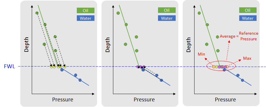
Image showing how the well pressure data points are being corrected to the reference depth. Min, Max, Average Calculated Well Pressure Data at Reference Depth (i.e. FWL in this case). click to enlarge
- Well Pressure Data Points The number of pressure measurements (i.e. the local measurements at specific points, assigned on the Assign Logs form). The total number of data points as well as the number of data points measured in gas, oil and water leg can be reviewed.
To set the reference pressure per compartment
- Select the fluid model of interest.
- Click the Autofill Reference Depth button () at the bottom-left corner of the form or enter a reference depth value manually.
- If you have provided the pressure log data, click the Autofill Reference Pressure button () at the bottom-left corner of the form or enter the reference pressure value manually.
- Click OK to set the pressure value at the reference depth and close the form, or click Apply to set the values and keep the form open.
The fluid model is now fully populated with information and can be used for Volumetrics Study. To prepare for this, use the Fluid Model Grid Properties option under the model > Fluids > Output Tools to make the fluid grid properties available in the Volumetrics Study workflow.
How 'Autofill Reference Depth' works
The Autofill Reference Depth button () populates the table with a recommended reference depth value per compartment. The autofilled reference depth per fluid compartment is filled based on the information entered on the Fluid Levels form. The following priority sequence is followed:
| GOC | FWL | Reference Depth |
|---|---|---|
| ✔ | None | GOC |
| ✔ | ✔ | GOC |
| None | ✔ | FWL |
| None | None | Average of TOP and BASE |
- If a GOC is specified on the Fluid Levels form, the reference depth is set to the GOC.
- If a GOC is not specified and a FWL is specified on the Fluid Levels form, the reference depth is set to the FWL.
- If neither GOC nor FWL are specified on the Fluid Levels form, the reference depth is set to the average of the shallowest and the deepest depth of a compartment, which are respectively specified as TOP and BASE on the Fluid Levels form.
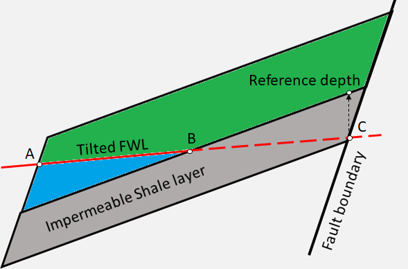
Image showing how the autofill reference depth is projected with a tilted free water level surface. The shallowest intersection point (point C) of the tilted FWL with the compartment boundary project vertically on the compartment boundary to estimate the reference depth. click to enlarge
How 'Autofill Reference Pressure' works
The Autofill Reference Pressure button () populates the table with a reference pressure value per compartment. It uses the fluid pressure data, i.e. the local measurements at specific points, which are assigned on the Assign Logs form. The autofilled reference pressure is the average of all the well pressure values corrected to the reference depth, i.e. Average Calculated Well Pressure at Reference Depth. See Calculated Well Pressure at Reference Depth for more on this. The wells that are taken into consideration are the assigned wellbores which intersect the compartment.
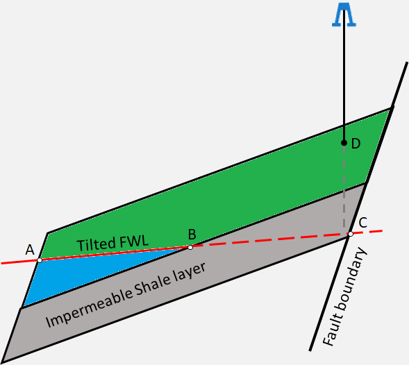
Image showing how the autofill reference pressure is calculated with a tilted free water level surface. The measured well pressure (point D) projects vertically on the tilted FWL (ABC) and calculates the reference pressure for the compartment. click to enlarge